Circuit Schematics
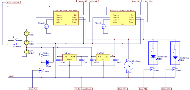
Our circuit was divided into 2 main boards, a Power board and a Sensor board. The power board connects the 3 batteries in series and provides power for all the actuators and the E128. The motor drivers were wired for a locked antiphase drive configuration and ran off of 21.6V. Our brush motor ran off 7V and our gate servo and LEDs ran off a regulated 5V. The 7V line is drawn away through another low dropout voltage regulator to a 5V sensor board, which powers our sensors and is separated from the actuators to reduce noise.
Main Power Board
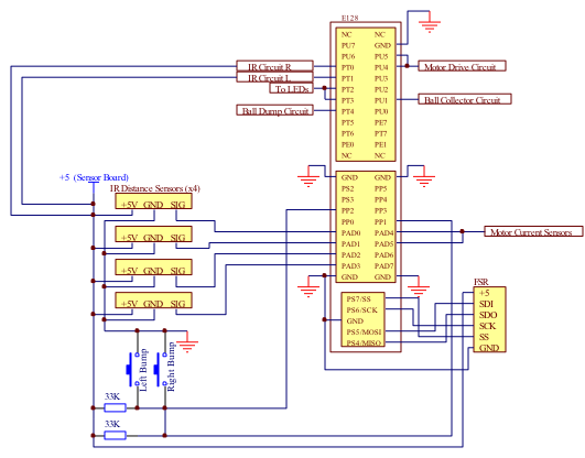
Microcontroller and Sensor Board
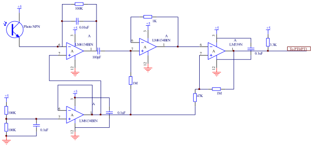
IR Beacon Detection Board
The IR Beacon Detection circuit started with the fundamental transresistive circuit. In the feedback stage of this op amp, a capacitor was included to create a low pass filter. This output was then fed through another operational amplifier with negative feedback to amplify the signal. This then went through a comparator to create a very clean, square signal. A unity gain buffer was used to provide all of the reference voltages for each stage circuit.